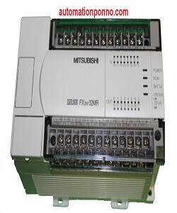
Mitsubishi MELSEC FX2N 32MR 001
Ask Price WhatsApp: +8801713-722455

Mitsubishi MELSEC FX2N 32MR 001
- Description
- Size Guide
- Reviews (0)
Description
The Mitsubishi MELSEC FX2N 32MR 001 is a digital I/O module designed for use with Mitsubishi FX series PLCs. It has 16 digital input & 16 digital output. This module FX2N 32MR 001 provides a versatile solution for expanding the digital input and output capabilities of the PLC system. Here’s a detailed description of its features, specifications, and typical applications:
Key Features Mitsubishi MELSEC FX2N 32MR 001Â
- Type: Digital Input/Output Module
- I/O Points:
- Digital Inputs: 16 points
- Digital Outputs: 16 points
- Voltage Rating:
- Inputs: DC 24V
- Outputs: DC 24V
Specifications Mitsubishi MELSEC FX2N 32MR 001
- Digital Inputs:
- Channels: 16 points
- Input Voltage: DC 24V
- Input Current: Approximately 3mA per point
- Input Type: NPN transistor input
- Input Impedance: Approximately 2.5kΩ
- Digital Outputs:
- Channels: 16 points
- Output Voltage: DC 24V
- Output Current: 0.1A per point, maximum 0.5A per module
- Output Type: NPN transistor output with short-circuit protection
| Mitsubishi PLC Module | FX2N and the FX2NC PLC’s Specification | Remarks |
| Operation control method | Cyclic operation by stored program | |
| I/O control method | Batch processing method (when END instruction is executed) | I/O refresh instruction is available |
| Operation processing time | Basic instructions: 0.08 msApplied instructions: 1.52 to several 100 ms | |
| Programming language | Relay symbolic language + step ladder | Step ladder can be used to produce an SFC style program |
| Program capacity | 8000 steps built in | Expandable to 16000 steps using additional memory cassette |
| Â Number of instructions | Basic sequence instructions: 20 Step ladder instructions: 2 Applied instructions: 125 | A Maximum 125 applied instructions are available |
| I/O configuration | Max hardware I/O configuration points 255, dependent on user selection (Max. software addressable Inputs 255, Outputs 255) | |
| Auxiliary relay(M coils) | 3072 points | M0 to M3071 |
| Auxiliary relay(M coils) | ||
| General | ||
| Auxiliary relay(M coils) | 2572 points (subset) | M500 to M3071 |
| Latched | ||
| Auxiliary relay(M coils) | 256 points | From the range M8000 to M8255 |
| Special | ||
| State relays (S coils) | 1000 points | S0 to S999 |
| General | ||
| State relays (S coils)Â Latched | 500 points (subset) | S500 to S999 |
| State relays (S coils)Â Initial | 10 points (subset) | S0 to S9 |
| State relays (S coils)Â Annunciator | 100 points | S900 to S999 |
| Timers (T)Â 100 msec | Range: 0 to 3,276.7 sec200 points | T0 to T199 |
| Timers (T)Â 10 msec | Range: 0 to 327.67 sec46 points | T200 to T245 |
| Timers (T)Â 1 msec retentive | Range: 0 to 32.767 sec4 points | T246 to T249 |
| Timers (T)Â 100 msec retentive | Range: 0 to 3,276.7 sec6 points | T250 to T255 |
| Counters (C)Â General 16 bit | Range: 1 to 32,767 counts200 points | C0 to C199Type: 16 bit up counter |
| Counters (C) | 100 points (subset) | C100 to C199Type: 16 bit up counter |
| General 16 bit | ||
| Latched 16 bit | ||
| Counters (C)Â General 16 bit | Range: -2,147,483,648 to 2,147,483,64735 points | C200 to C234Type: 32 bit up/down counter |
| General 32 bit | ||
| Counters (C)Â General 16 bit | 15 points (subset) | C219 to C234Type: 16 bit up/down counter |
| Latched 32 bit | ||

Applications:
- Factory Automation: Ideal for controlling machines, conveyors, and other automated systems that require digital I/O signals.
- Process Control: Used in applications requiring the control of various digital devices and actuators.
- Building Automation: Suitable for controlling lighting, HVAC systems, and other building management tasks.
Benefits:
- Compact Design: Space-saving design suitable for installation in control panels with limited space.
- Reliability: Robust construction ensures reliable performance in industrial environments.
- Ease of Installation: Designed for quick and easy installation on a DIN rail, with clear labeling for straightforward wiring.
Installation and Configuration:
- Mounting:
- Secure the FX2N-32MR-001 module on a DIN rail inside a control panel.
- Wiring:
- Connect the digital inputs and outputs to the appropriate terminals, following the wiring diagrams provided in the user manual.
- Software Setup:
- Use Mitsubishi’s GX Works2 or GX Works3 software to configure the module.
- Define the digital input and output points.
- Set the input and output parameters, such as input logic type and output control settings.
- Integrate the module into your PLC program and define the control logic.
- Use Mitsubishi’s GX Works2 or GX Works3 software to configure the module.
- Testing:
- Download the configuration to the PLC.
- Use the PLC’s diagnostic tools to monitor and verify the operation of the digital inputs and outputs.
- Conduct thorough testing to ensure all digital signals are correctly processed and controlled.
The FX2N-32MR-001 is a reliable and efficient digital I/O module for Mitsubishi FX series PLCs. It provides 16 digital input and 16 digital output points, making it suitable for a wide range of industrial automation applications. Proper installation and configuration using Mitsubishi’s software tools will ensure that the module operates effectively in your control systems.


Reviews
There are no reviews yet.